Lantronix
Xport Configuration
Adding
the Xport
In HW version 1.0, the Xport devices is installed on the
bottom side of the PCB. Unfortunately the Lantronix Xport does not match
into the Box Kit since there is too few space between the box and the PCB.
It all requires a 38mm inside high box for this selection.
|
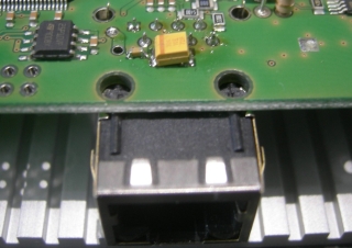
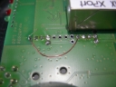
Adding two capacitors (provided with Xport, maybe I will pre-do this for those ordering Xports) to the top side of the PCB The small capacitor on the left side is 100nF, size 0603 The
larger one on the right side is 10µF...47µF, minimum 5V There is no need to cut the two mounting pins of the Xport as I did! |
|
|
Install
the Xport on the bottom side of the PCB |
|
|
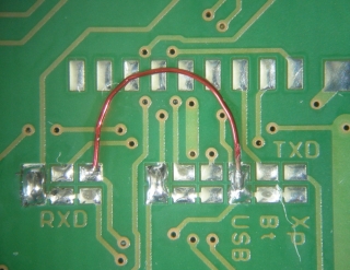
Adding
a small wire bridge at the RS232 multiplexer for the TxD signal. (most
probable I will pre-do this for those ordering Xports) As you see it here, the output is routed to USB and Xport in parallel, while RTS and the eventual RxD input are routed to USB only. |
|
Standalone 5V Power
Supply
|
|
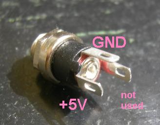
External 5V power can be supplied through the two solder pads on the board, here in the upper right corner. Recognize the pad with 4 connections to the ground plane, this is [-], the other one is [+]. Any power supply should have 5V/1A minimum in order to ensure fast enough raise time that is needed for a safe reset. |
|
|
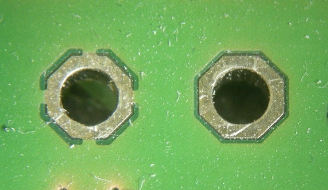
DC input pads: Here in large scale: Left side the pad with four connections to the ground plane is GND, the other one without is +5V |
|
|
The power supply connector is connected as shown on the right side The pad that is not used can be removed |
Box
Mounting
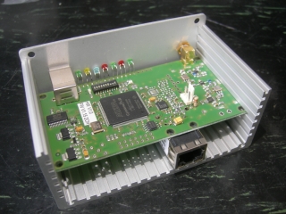
The
standard box does not fit for the Xport, since there is too less space below
the PCB. I found a bigger box with an inside height of 38mm that fits both, an
Xport and an additional miniADSB. See here some impressions of how that was
done.
|
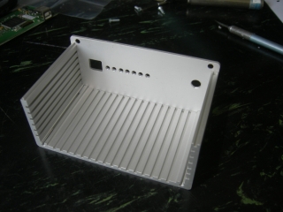
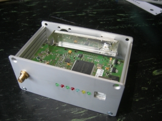
This is the 38mm high box, it is a different style as the box kit. Front panel was drilled using the predrilled front panel as template |
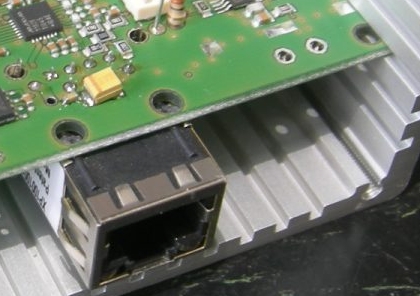
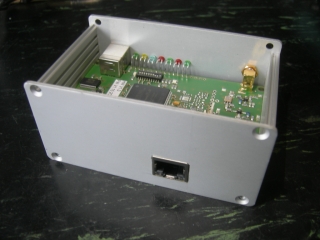
The box is cut for 62mm length, so the Xport fits perfectly to the back wall. In the next HW Version I will place the Xport to the upper
side of the PCB and also towards the front panel. |
|
|
|
Xport
Configuration
Note: When using a Xport you have
to set the RS232 baudrate to 921800 bit/sec. If you want to use two devices in
parallel, like USB and Xport, it might work that the FT232R is configured for
1MBit in parallel. Otherwise you have to select a common baudrate, which is for
example 115200 bits/sec for Xport and RS232.
Please be aware that the Xport is a network device and needs some higher
sophisticated configuration!
Setting up for TCP mode
Xport Network Setup Important Note: While configuring, you always have to press "OK" button at the bottom, plus "Apply Settings" in the left hand menu. |
Xport Server Settings |
Xport Connection Settings |
Xport Serial Settings |
Setting
up for UDP mode
This
mode is used in order to directly transfer data from the Mode-S Beast over the
network to Planeplotter.
|
Planeplotter
Setup |
Xport
Network Setup |
Xport
Server Settings |
Xport
Connection Settings |
Xport
Serial Settings |
The network load on a 100MBit LAN is quite low, I was surprised that it was
less than 1%.
Setting
up for TCP mode / COM port over Ethernet
In the same way there is a driver for a virtual COM port
that appears on the PC as serial interface. This way or some properitary modes
require TCP configuration of the Xport.
If you cannot interface the UDP or TCP data into your application but need a
COM port, have a look for the Lantronx
Com Port Redirector.
FAQ
- Q: Is there a way to factory reset the Xport direct
without using serial?
A: telnet to port 9999. Then you get a simple console menue, much like the BIOS setup of your PC. Simply do a factory reset, save and exit, and after a moment you will have it back on factory defaults.
- Q: How do I upgrade the Firmware of the Lantronix Xport
A: There is a FAQ of Lantronix, but ensure that the hardware revision of the Lantronix matches to that.