The External miniADSB Connection:
There
is an option of connecting up to three external 1090MHz receivers to the board.
Any receiver that has an amplitude dependent output would fit here, but mostly
recommended is the so called miniADSB receiver from Andy at jetvision.de. See
its own web page on http://miniADSB.web99.de.
For each external miniADSB, you need to add a 33R resistor and a 3pin connector to the Mode-S Beast board. These parts, together with a fitting 3pin cable, is delivered one time with the 2CH version and three times with the 4CH device. I strongly recommend using them because they ensure correct polarity of the connection.
|
|
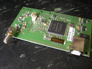
Here
you can see the connector for the miniADSB on the 2CH Mode-S Beast. Behind
the connector there is a 33 Ohm standard resistor, which
|
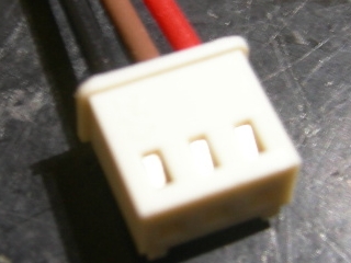
The pinning the cable is
|
Pin
Location |
Pin Number |
Usage |
|
towards
resistor |
1 |
+4,5V
supply |
|
middle |
2 |
GND |
|
opposite
side of resistor |
3 |
Signal
input |
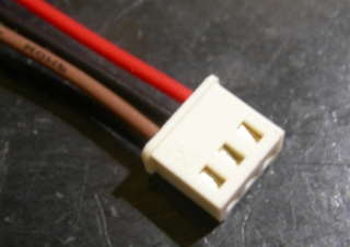
Before using the cable, please swap the brown and the black wire
Before using the cable, please swap
the brown and the black wire, so that you get black=GND in the center, red=+5V
towards the 33R resistor and brown=signal on the opposite side:
|
|
|
|

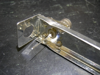
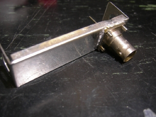
The
ready made miniADSBs that I deliver do have a right angle mounted BNC
connector:
|
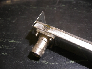
I am using flange mounted connectors with M2,5 threads For soldering, I am fixing
these from the inner side. The screws are part of the ready made miniADSB kit. |
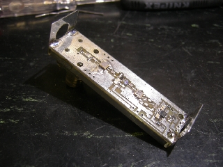
From the other side The BNC connector is soldered to the box. Note the two bends on the top and bottom along the BNC, which is later for the GND connection of the miniADSB board. The center pin of the
connector is extended with a piece of wire |
Fit the PCB into the box Since the whole of the former BNC connector is below Lambda/10 of 1090MHz, there is no urgency to close it. If you really like, simply solder two wires in X or + shape across it. Do not
forget to remove the screws before soldering. |
Solder the miniADSB board to the box also at the gap bends you've done before. |
Ready to be connected and tested