Für jedes externe miniADSB, müssen Sie einen 33R Widerstand und einem 3pin Anschluss mit dem Mode-S Beast Board hinzuzufügen. Diese Teile, zusammen mit einem passenden 3pin-Kabel, wird einmal mit dem 2CH-Version und dreimal mit dem 4-Kanal-Gerät geliefert. Ich empfehle nur die weil sie die richtige Polarität der Verbindung gewährleisten.
|
|
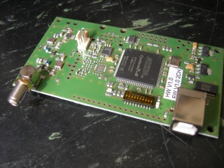
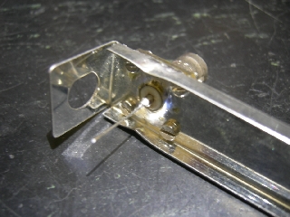
Hier sehen Sie den Stecker für den miniADSB auf die 2CH Mode-S Beast. Hinter dem Stecker befindet sich ein 33 Ohm Standard-Widerstand, der ein wenig Spannungsabfall und Schwingung des miniADSB vermeidet.Die Widerstände sind eine Sicherung für den Fall, dass etwas wirklich schief läuft. |
The pinning the cable is
| Pin Location | Pin Number | Usage |
| towards resistor | 1 | +4,5V supply |
| middle | 2 | GND |
| opposite side of resistor | 3 | Signal input |
Vor dem verwenden bitte tauschen Sie den braunen und der schwarzen Draht
Before using the cable, please swap the brown and the black wire, so that you get black=GND in the center, red=+5V towards the 33R resistor and brown=signal on the opposite side:
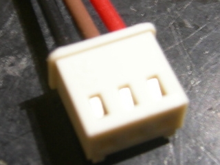 The original pinning of the cable has misleading colors |
 With a thin pin like a needle or sharp tweezers, carefully press down the lock spring of the cable and easily pull out the cable towards left. If you press the lock too far, reverse bend it from the inner side of the contact |
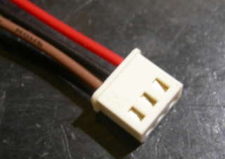 The final color coding of the connector is much more senseful. |
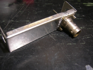
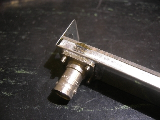
 I am using flange mounted connectors with M2,5 threads For soldering, I am fixing these from the inner side.Later, the miniADSB can be mounted to the rear wall with these for M2.5 screws. The 5 drills are made with CNC machine and fit perfectly. The screws are part of the ready made miniADSB kit. |
From the other side The BNC connector is soldered to the box. Note the two bends on the top and bottom along the BNC, which is later for the GND connection of the miniADSB board. The center pin of the connector is extended with a piece of wire |
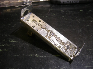 Fit the PCB into the box Since the whole of the former BNC connector is below Lambda/10 of 1090MHz, there is no urgency to close it. If you really like, simply solder two wires in X or + shape across it. Do not forget to remove the screws
before soldering. |
 Solder the miniADSB board to the box also at the gap bends you've done before. |